Cable Tray Installation: What NEC 392 Requires
October 14, 2026 | Samantha Mariano
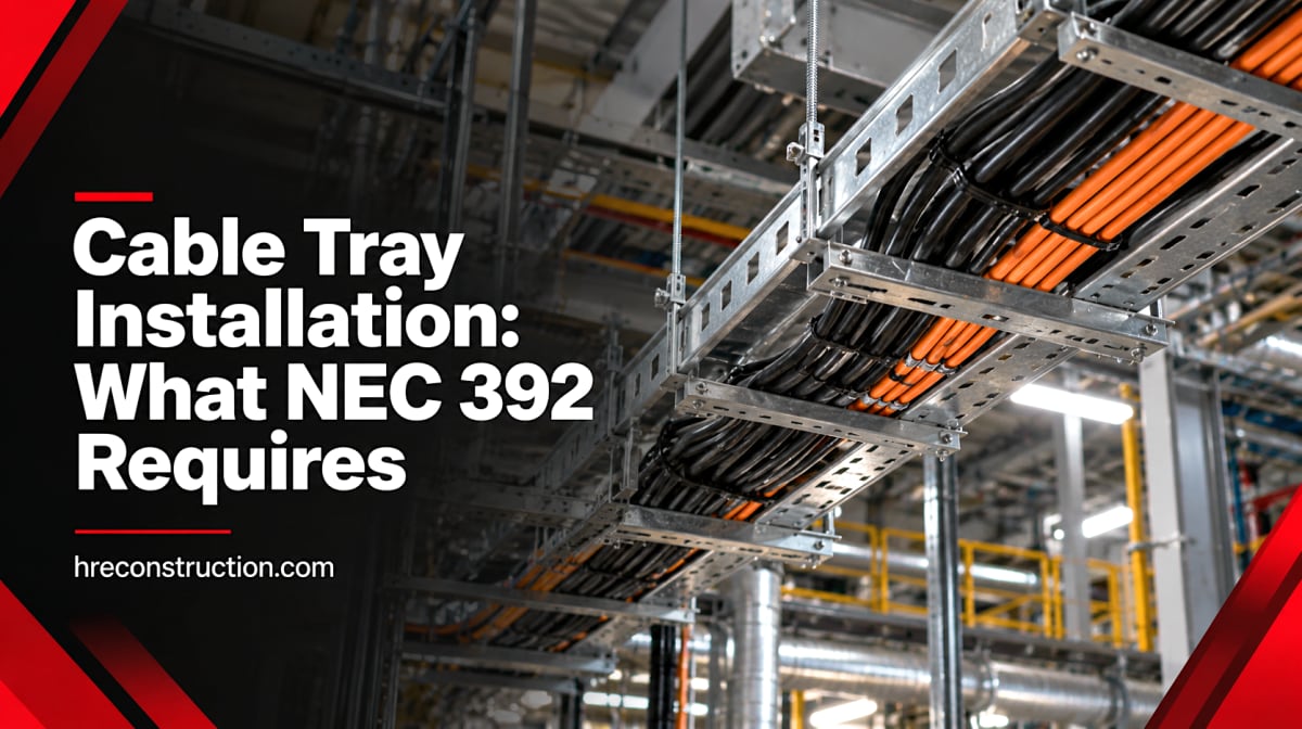
Walk through almost any manufacturing plant and look up. Above the production floor, running across the bays and dropping down to motors, drives and control panels, you'll usually find cable tray. It's the backbone of industrial power and control distribution because it carries a lot of cable, it's easy to add to, and it costs less per circuit than running everything in conduit.
That flexibility is also where problems start. A tray that was installed correctly ten years ago can be overfilled, poorly bonded and out of code today, simply because circuits kept getting added without anyone checking the math. NEC Article 392 sets the rules for cable tray installation, and the 2026 edition added a new one worth knowing about.
Here's what facility managers and plant engineers should understand about cable tray requirements, from fill and ampacity to grounding and access.
Cable Tray Is a Support System, Not a Raceway
This is the starting point for everything else in Article 392. A cable tray is a support system for cables. It is not a raceway like conduit, so the cables in it have to be wiring methods that are allowed in tray on their own.
NEC 392.10 lists what's permitted. In industrial work, that usually means Type TC (power and control tray cable), Type MC, Type MV for medium voltage, and instrumentation tray cable, along with other listed cable types. Single insulated conductors are only allowed under the specific conditions in 392.10(B)(1), and generally only in sizes 1/0 AWG and larger in ladder, ventilated trough or ventilated channel tray.
Cable tray is also not limited to industrial buildings. The Code permits it in commercial and institutional occupancies too, as long as the installation complies. What it doesn't allow is tray in hoistways or where it would be subject to severe physical damage.
Common Cable Tray Types
| Tray Type | Best For | Notes |
| Ladder | Large power feeders, long spans | Best airflow, easiest cable access |
| Ventilated trough | Mixed power and control | Continuous ventilated bottom gives more cable support |
| Solid bottom | Instrumentation and signal cable | More noise protection, but lower fill limits |
| Channel | Small drops and a few cables | Narrow, often used for branch runs |
| Wire mesh (basket) | Control, data and light power | Easy field changes, check its rating before using it as a grounding path |
Cable Tray Fill: How Much Can You Put In?
Fill is the requirement most often violated in existing plants. NEC 392.22 sets the limits, and they depend on the tray type, the cable type and the cable size. For multiconductor cables rated 2000 volts or less in ladder or ventilated trough tray:
- Cables 4/0 AWG and larger: The sum of the cable diameters can't exceed the tray width, and the cables must lie in a single layer.
- Cables smaller than 4/0 AWG: The sum of the cables' cross-sectional areas can't exceed the allowable fill area in Column 1 of Table 392.22(A) for that tray width.
- A mix of both: Large cables go in a single layer, and the smaller cables are limited by a reduced fill area from Column 2 of the same table.
- Control and signal cable only: Fill is limited to 50 percent of the tray's inside cross-sectional area in ladder or ventilated tray, and 40 percent in solid bottom tray.
Solid bottom tray has lower fill limits than ladder tray for power cable, because heat has a harder time escaping.
A Quick Fill Example
A 24-inch ladder tray has an allowable fill area of 28 square inches in Column 1 of Table 392.22(A). Say you're running multiconductor power cables with a 0.75-inch outside diameter. Each cable has a cross-sectional area of about 0.44 square inches (pi times the radius squared). Divide 28 by 0.44 and you get a maximum of 63 of those cables.
That's the code limit. It isn't the only limit. The tray also has a load rating, and a heavily loaded tray on a long support span can hit its weight limit before it hits its fill limit. Cable tray is typically specified by a load and span class under NEMA VE 1, so check that the tray and support spacing can carry the full cable weight, including cable you plan to add later.
Ampacity in Cable Tray Works Differently
Ampacity rules for tray are in NEC 392.80, and they don't follow the same logic as conduit. That catches people on both sides, sometimes oversizing cable for no reason, sometimes undersizing it.
For multiconductor cables rated 2000 volts or less:
- The usual starting point is Table 310.16. Adjustment factors for bundling only apply to cables with more than three current-carrying conductors, and they're based on the conductors inside each cable, not the total number of cables in the tray. That's the big difference from conduit.
- Covered tray costs you ampacity. Where the tray is continuously covered for more than 6 feet with solid, unventilated covers, the cables are limited to 95 percent of the table values.
- Spacing can earn you more. Where multiconductor cables are installed in a single layer in uncovered tray with at least one cable diameter between them, ampacity can be based on the free-air values in 310.15(C).
Single-conductor cables have their own set of rules in 392.80(A)(2), based on percentages of the free-air ampacity tables, with lower percentages again where the tray is covered. Medium-voltage cables over 2000 volts are covered separately in 392.80(B).
Ambient temperature still matters. Tray run near ovens, furnaces, boilers or along a hot roof deck needs temperature correction like any other installation. Our post on cable sizing and wire management covers how ambient heat and terminal ratings stack up.
Separating Medium-Voltage and Low-Voltage Cable
Plants that run medium-voltage feeders often want to use the same tray for 480-volt power. NEC 392.20 doesn't allow that unless there's a solid fixed barrier of a material compatible with the tray between the two voltage classes, or the medium-voltage cables are Type MC.
Separating power from instrumentation and signal cable isn't always a code requirement, but it's good practice. Running 4-20 mA signals and drive output cables side by side in the same tray is a common source of noisy readings. Barrier strips or a separate solid bottom tray for instrumentation solve most of it.
When single conductors are used, all conductors of a circuit, including the neutral and equipment grounding conductor where present, should be grouped together. Spreading phases apart can cause inductive heating in the tray and unbalanced current in parallel sets.
Grounding and Bonding Cable Tray
NEC 392.60 covers grounding and bonding. Metal cable tray that supports electrical conductors has to be bonded and grounded like any other conductor enclosure, and the tray system has to be electrically continuous. At splices, expansion joints and gaps, that continuity comes from approved connections or bonding jumpers.
Metal tray can also serve as the equipment grounding conductor, but only under specific conditions:
- Continuous maintenance and supervision ensure that only qualified persons service the tray system.
- The tray side rails meet the minimum cross-sectional metal area in Table 392.60(A) for the size of the overcurrent device protecting the largest circuit.
- The tray and its fittings are identified for use as an equipment grounding conductor.
- Every section and fitting is effectively bonded so it can safely carry any fault current likely to be imposed on it.
Even metal tray that only carries non-power cables, like fiber or Class 2 circuits, has to be electrically continuous, using approved connections or a bonding jumper no smaller than 10 AWG.
Two practical points come up often in the field. Bare copper grounding conductors shouldn't be laid in aluminum tray, because of the risk of galvanic corrosion in damp environments. And many manufacturers recommend against using wire mesh tray as the grounding path, so a separate equipment grounding conductor is the safer choice there. For the bigger picture on fault paths, see our post on grounding and bonding in industrial facilities.
The New 2026 NEC Rule: 12 Inches of Access Above the Tray
Previous editions of NEC 392.18(F) only required "sufficient space" above and around cable tray for installing and maintaining cables. That left the definition of "sufficient" up to the installer and the inspector, and enforcement varied.
The 2026 NEC replaced that with a number. A minimum of 12 inches of access space must be provided and maintained above cable trays. There are four exceptions:
- IT equipment rooms that comply with 645.5.
- Industrial establishments where maintenance and supervision ensure only qualified persons service the cable tray.
- Smaller spacing granted by special permission from the authority having jurisdiction.
- Equipment crossing over the tray at any angle.
Exception 2 will cover a lot of industrial plants, but it doesn't make access irrelevant. A tray tucked tight against a roof deck or buried under ductwork is still hard to work on, and every future cable pull costs more for it. If you're designing a new tray route, planning for 12 inches is the simpler path. Keep in mind that adoption of the 2026 NEC varies by state, so confirm which edition your jurisdiction enforces. Our overview of what the 2026 NEC update means for industrial facilities covers the other changes.
The 2026 NEC also added a requirement in 300.13(E) that cable ties used to secure and support wiring be listed. That applies to cable tray installations too, so the bag of generic ties on the truck may not pass anymore.
Getting Cable From the Tray to the Equipment
Standard Type TC cable has to stay inside the tray or a raceway. To leave the tray and run exposed to a motor, drive or panel, the cable needs to be Type TC-ER (exposed run), which has passed additional crush and impact testing.
Under NEC 336.10, TC-ER is permitted in industrial establishments where only qualified persons service the installation. Exposed runs need to be continuously supported and protected from physical damage, and secured at intervals not exceeding 6 feet. Where it isn't subject to physical damage, TC-ER can span up to 6 feet between the tray and the equipment without continuous support.
Tray cable is also limited in hazardous areas. Type TC is permitted in Class I, Division 2 locations, but Division 1 areas generally require MC-HL cable or rigid conduit. Our post on classified locations and NEC Article 500 explains how those areas are defined.
Common Cable Tray Problems in Existing Plants
When we walk an older facility, these are the issues we find most often:
- Overfilled trays. Years of added circuits, with old abandoned cables still in place taking up room.
- Missing bonding jumpers. At expansion joints, broken splices and gaps where a tray section was cut to clear new equipment.
- Tray used as the ground without the right conditions. No Table 392.60(A) check, or a wire mesh tray carrying the only fault path.
- Standard TC cable dropping to equipment. Exposed runs that should be TC-ER or in conduit.
- Sagging spans. Supports spaced too far apart for the actual cable weight, or supports removed during a remodel.
- No room to work. New ductwork, piping or sprinkler lines installed tight against the top of the tray.
- Damaged cable left in place. The 2026 NEC added language in 300.4(C) requiring wiring that's no longer suitable for use to be replaced.
Most of these don't cause a problem the day they happen. They show up later as hot cables, nuisance trips, noisy instrument signals or a ground fault that doesn't clear the way it should.
How HRE Can Help
HRE Construction designs and installs cable tray systems for industrial facilities, from new tray routes for plant expansions to rework of existing trays that have outgrown their original layout. We check fill and ampacity against NEC Article 392, confirm the tray and supports can carry the real cable weight, verify bonding across every splice and joint, and make sure exposed drops to equipment use the right cable type.
If you're adding equipment, our team can review whether your existing tray has room or whether a new route makes more sense, as part of broader electrical capacity planning. And when the installation is complete, we can verify it through electrical commissioning before it goes into service. Learn more about our industrial electrical installation services.
Plan Your Next Cable Tray Project With HRE
Whether you're building a new line or untangling a tray that's been added to for twenty years, getting the tray right up front saves money on every cable pull after it.
Contact HRE Construction at 803-262-2615 to talk through your cable tray installation or request a quote.
Frequently Asked Questions
What is the NEC article for cable tray?
NEC Article 392 covers cable tray systems, including permitted uses, installation, fill, grounding and ampacity. The tray cable itself, Type TC and TC-ER, is covered separately in Article 336.
How full can a cable tray be?
It depends on the tray type and cable size. For multiconductor power cables smaller than 4/0 AWG in ladder or ventilated tray, total cable area can't exceed Column 1 of NEC Table 392.22(A). For control and signal cable only, fill is limited to 50 percent of the tray's cross-sectional area in ladder tray and 40 percent in solid bottom tray.
Can a cable tray be used as a ground?
Yes, in some cases. Metal cable tray can serve as an equipment grounding conductor where only qualified persons service it, the side rails meet the metal area in Table 392.60(A), the tray is identified for that use, and every section is effectively bonded.
What is the 2026 NEC 12-inch cable tray rule?
NEC 392.18(F) in the 2026 edition requires at least 12 inches of access space above cable trays. Exceptions include IT rooms complying with 645.5, industrial establishments with qualified-person maintenance, special permission from the AHJ, and equipment crossing the tray.