Why Motors Fail on VFDs: Reflected Waves and Bearing Currents
October 15, 2026 | Samantha Mariano
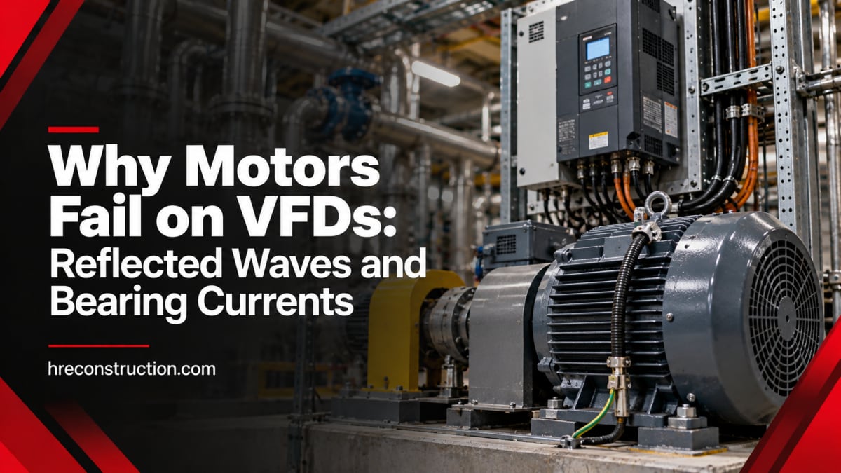
Variable frequency drives are one of the best upgrades an industrial facility can make. They cut energy use on fans and pumps, soften motor starts, and give operators real control over speed. That's why so many plants have added them over the last decade.
But a pattern shows up in a lot of those plants. A motor that ran for fifteen years across the line starts failing every year or two once it's put on a drive. Sometimes the windings short. Sometimes the bearings start howling after a few months. The drive gets blamed, the motor gets rewound or replaced, and the same thing happens again.
In most of these cases, the drive and the motor are both fine. The problem is how they were put together. Here's what's actually happening, how to spot it early, and what fixes it.
Why a VFD Is Hard on a Motor
A VFD doesn't send a smooth sine wave to the motor. It rectifies incoming AC to DC, then switches that DC on and off thousands of times per second to build a simulated AC waveform. This is called pulse width modulation (PWM).
Each of those pulses rises extremely fast. Modern drives use IGBT switches that can go from zero to full voltage in a fraction of a microsecond. That speed is what makes drives efficient, but it creates two side effects that standard motors were never designed for:
- Voltage spikes at the motor terminals (reflected waves), which attack the winding insulation.
- Common-mode voltage on the motor shaft, which discharges through the bearings.
These are two separate problems with separate fixes, and plenty of motors deal with both at once.
Problem 1: Reflected Waves and Insulation Failure
When a fast pulse travels down the cable from the drive to the motor, it hits a mismatch. The motor's impedance is much higher than the cable's, so part of the pulse reflects back and adds to the next one. The result is a voltage overshoot at the motor terminals that can be far higher than the drive's normal output voltage.
On a 480-volt system, the U.S. Department of Energy has reported measured spikes as high as 2,150 volts at the motor. Repeated thousands of times a second, those spikes wear down the winding insulation until it breaks down, causing phase-to-phase or turn-to-turn shorts and drive trips.
What Makes Reflected Waves Worse
- Longer motor leads. The longer the cable between the drive and the motor, the bigger the overshoot. The DOE notes that reflected waves generally aren't a concern when the drive is within about 15 feet of the motor, and the risk climbs from there. Each drive manufacturer publishes its own maximum lead lengths, and those are the numbers to follow.
- Faster switching. Drives with faster rise times and higher carrier frequencies produce more overshoot.
- Smaller motors. Smaller motors have higher impedance, which makes the mismatch worse.
- One drive running several motors. Multiple motor leads off one drive multiply the reflections.
What the Motor Standard Says
NEMA MG 1 sets the voltage a motor should be able to handle on a drive:
| Motor Type | NEMA MG 1 Section | Peak Voltage Limit | Minimum Rise Time |
| General-purpose motor (600 V or less) | Part 30 | 1,000 V | 2 microseconds |
| Definite-purpose inverter-duty motor (600 V or less) | Part 31 | 3.1 x rated line-to-line voltage (about 1,426 V for a 460 V motor) | 0.1 microsecond |
The gap between those two rows is the whole story. A general-purpose 460-volt motor is only expected to handle 1,000-volt peaks, and a drive on a long lead can easily exceed that. An inverter-duty motor built to Part 31 has insulation designed for the spikes a drive actually produces.
Lower-voltage systems are less of a concern. A 208 or 230-volt motor typically uses the same insulation system as a 460-volt motor, so drive spikes on those systems rarely damage it.
How to Fix Reflected Wave Problems
- Use inverter-duty motors. For new installs and replacements on drives, specify motors that meet NEMA MG 1 Part 31.
- Keep motor leads short. Mount the drive as close to the motor as the layout allows, and stay inside the drive manufacturer's lead length limits.
- Add output filtering when leads have to be long. A load reactor or dv/dt filter at the drive output slows the voltage rise and reduces the overshoot. For very long runs, a sine wave filter smooths the output close to a true sine wave, at the cost of more size, heat and money.
- Check existing motors before adding a drive. Retrofitting a drive onto an older general-purpose motor is common, and it can work, but the motor's insulation and the lead length need to be checked first.
Problem 2: Bearing Currents and Fluting
The second problem is less obvious and often misdiagnosed as a lubrication or alignment issue.
A PWM drive's three output phases never add up to zero the way a clean sine wave supply does. The leftover is called common-mode voltage. It couples through the motor's internal capacitance onto the rotor and shaft. When that shaft voltage builds high enough, it discharges to ground through the easiest path it can find, which is usually the bearings.
Each discharge arcs across the thin film of grease between the balls and the race and melts a tiny pit in the metal. This is called electrical discharge machining (EDM). One pit doesn't matter. Millions of them do. First the race turns dull and gray, a condition called frosting. Over time, the damage settles into evenly spaced ridges across the race, known as fluting, which looks like a washboard.
Warning Signs of Bearing Currents
- A motor that starts making a whining, growling or rumbling noise within months of being put on a drive
- Rising vibration readings, often at bearing-related frequencies
- Bearings that fail on the same motor again and again, even after replacement and alignment checks
- A frosted or washboard pattern on the race when a failed bearing is cut open
That last sign is the giveaway. If a failed bearing shows fluting, replacing it with the same bearing just restarts the clock.
How to Fix Bearing Currents
- Give the current a better path. A shaft grounding ring or brush gives shaft voltage a low-resistance path to ground that bypasses the bearings. This is one of the most common and cost-effective fixes.
- Break the path through the bearing. Insulated bearings or hybrid bearings with ceramic balls stop current from passing through the motor bearing. The catch is that the shaft voltage is still there and will look for another way out, often through the coupling into a gearbox or pump bearing. That's why insulated bearings are usually paired with a shaft grounding ring, especially on larger motors, which can also develop circulating bearing currents. Recommendations vary by motor size and manufacturer, so follow the motor maker's guidance for the specific frame.
- Use proper VFD cable. Symmetrical, shielded VFD cable with the shield bonded at both the drive and the motor gives high-frequency current a path back to the drive instead of through the motor and the driven equipment.
- Bond the motor frame to the drive. A low-impedance bond between the motor frame and the drive ground keeps high-frequency current where it belongs. Our post on grounding and bonding in industrial facilities covers the bigger picture.
- Review the carrier frequency. A lower carrier frequency means fewer pulses per second, though it can make the motor louder. It's a setting worth reviewing with the drive manufacturer's guidance during startup, not a fix on its own.
- Skip conductive grease as a fix. It can seem like an easy answer, but the conductive particles add mechanical wear to the bearing.
Other Ways Drives Shorten Motor Life
Reflected waves and bearing currents get the most attention, but a few other issues show up in drive installations:
- Low-speed overheating. A standard TEFC motor's cooling fan slows down with the motor. Run it at low speed and full torque for long periods and it overheats. Check the motor's rated speed range on a drive, and consider a separately powered cooling blower for continuous low-speed duty.
- Harmonics on the supply side. Drives draw non-sinusoidal current that can distort voltage for other equipment in the plant. That's a separate issue from motor damage, and we cover it in our post on harmonic distortion.
- Poor cable routing. Running drive output cables alongside instrumentation and control wiring causes noise problems. Keep them separated in the tray, as we explain in our cable tray installation guide.
Catching VFD Motor Problems Early
Most of these failures give warning before they stop a line. A few checks go a long way:
- Insulation resistance testing on drive-fed motors as part of routine maintenance. Trending the readings over time tells you more than any single number, as we explain in our post on what Megger readings reveal.
- Vibration monitoring to catch bearing damage while it's still a planned repair, as part of a broader predictive maintenance program.
- Inspecting failed bearings instead of just throwing them out. A fluted race tells you the next bearing will fail the same way unless something changes.
- Measuring at the motor terminals with the right equipment when a motor fails repeatedly, to see the actual peak voltage and rise time the motor is seeing.
How HRE Can Help
HRE Construction installs and troubleshoots variable frequency drives and motor circuits in industrial facilities. When we install a drive, we look at the whole system: the motor's insulation rating, the cable type and lead length, the bonding between the drive and the motor, and whether filtering or bearing protection is needed for that application.
When a motor keeps failing on a drive, we track down the cause instead of replacing parts and hoping. That can mean checking lead lengths and drive settings, testing insulation, reviewing cable and grounding, and recommending the right fix, from an output filter to a shaft grounding ring or an inverter-duty replacement. Learn more about our industrial electrical installation services and our testing and startup services. If you're still deciding where drives make sense in your plant, our post on VFDs in industrial energy management is a good place to start.
Stop Replacing the Same Motor
A motor that keeps failing on a drive is telling you something about the installation. Fixing the cause costs less than the next rewind and the downtime that comes with it.
Contact HRE Construction at 803-262-2615 to have our team look at your drive-fed motors or plan your next VFD installation.
Frequently Asked Questions
Why do motors fail when connected to a VFD?
The two most common causes are reflected wave voltage spikes, which break down winding insulation, and bearing currents, which pit and flute the bearings. Both come from the fast-switching pulses a drive produces and are made worse by long motor leads, poor cabling and missing bonding.
What is an inverter-duty motor?
An inverter-duty motor is built to handle the voltage stress of a drive. Under NEMA MG 1 Part 31, a motor rated 600 volts or less should withstand peaks up to 3.1 times its rated voltage with rise times as fast as 0.1 microsecond. A general-purpose motor under Part 30 is only expected to handle 1,000-volt peaks.
What is bearing fluting?
Fluting is a washboard pattern of ridges worn into a bearing race by repeated electrical discharges. It's caused by common-mode voltage from a VFD discharging through the bearing, and it shows up as noise, vibration and repeated bearing failures.
How do you stop VFD bearing currents?
Common fixes include a shaft grounding ring or brush, insulated or ceramic hybrid bearings, symmetrical shielded VFD cable bonded at both ends, and a good bond between the motor frame and the drive. The right combination depends on the motor size and the installation.