HRE Construction / Industrial Electrical
Thermowells: How to Size, Select, and Avoid Failures
November 12, 2026 · 11 min read · By HRE Construction

A thermowell is the least exciting part of a temperature measurement point. It has no electronics and no display, and nobody thinks about it until something goes wrong. But the thermowell is the part that sits in the flow, holds back process pressure, and gets shaken by the fluid moving past it. When it is sized wrong, you get slow or inaccurate readings. In the worst case, the well cracks and the process leaks.
This guide covers what a thermowell does, the dimensions and design choices that matter, why some thermowells fail from vibration, and what to check on the ones already installed in your plant.
What a Thermowell Does
A thermowell is a pressure-tight sleeve, usually machined from solid bar stock, that goes into a pipe or vessel and holds a temperature sensor. It has two main jobs:
- Protect the sensor from process pressure, flow forces, and corrosive or abrasive media.
- Let you remove the sensor for calibration or replacement without draining the line or shutting down the process.
The trade-off is response time. The process has to heat the mass of the thermowell before it heats the sensor, so a sensor in a well will always respond more slowly than a bare sensor in the same flow. Good thermowell design is about keeping that penalty small while keeping the well strong enough for the service.
Thermowell vs. Thermocouple: Not the Same Thing
People mix these up all the time, so it is worth a quick clarification. The thermocouple or RTD is the sensor. It produces the signal. The thermowell is the housing that the sensor slides into. One thermowell might hold an RTD today and a thermocouple after a future upgrade, as long as the bore and length fit.
The usual order is to pick the sensor first, then pick a thermowell that matches the sensor diameter and survives the process. If you are still deciding on the sensor, our guide on RTD vs. thermocouple selection covers accuracy classes, drift, and wiring.
The Dimensions That Matter
When you order a thermowell, a few dimensions do most of the work:
- Insertion length (U): the distance from the process connection to the tip. This is the part that sits in the process.
- Lagging extension (T): extra length between the process connection and the instrument connection so the head clears pipe insulation.
- Bore: the hole the sensor goes into. Common bores are 0.260 in. for a 1/4 in. sensor and 0.385 in. for a 3/8 in. sensor. A close fit matters (more on that below).
- Root and tip diameter: the outside diameter where the well meets the connection and at the tip. These drive both strength and response.
How long should a thermowell be?
There are two competing goals. A longer well gets the sensor deeper into the flow and reduces conduction error, which is heat loss along the stem back to the pipe wall. A common rule of thumb from ISA is an immersion length of at least 10 times the thermowell diameter to keep conduction error down, with the tip reaching toward the middle of the pipe.
But a longer well is also more flexible and more likely to vibrate. That is the core conflict in thermowell design, and it is why "just make it longer" is not a safe answer in high-velocity service. Rules of thumb are a starting point. The vibration check described below is what confirms the length.
Stem Profiles: Straight, Tapered, and Stepped
The shape of the stem affects strength, response time, and drag.
| Stem profile | What it looks like | Strengths | Trade-offs |
|---|---|---|---|
| Straight | Same diameter from root to tip | Simple and robust | Most material at the tip, so the slowest response and the most drag |
| Tapered | Diameter shrinks gradually toward the tip | Good balance of strength and response; very common in process plants | Costs more to machine than straight |
| Stepped | Full diameter near the root, then a smaller diameter section at the tip | Least material at the tip, so the fastest response and least drag | Smaller tip needs a strength check for the service |
When wall thickness and sensor fit are equal, a stepped well responds fastest and a straight well responds slowest. Tapered and stepped designs also tend to hold up better against flow-induced vibration than a straight well of the same length.
Process Connection Types
How the thermowell attaches to the pipe affects installation, maintenance, and pressure capability.
| Connection | How it attaches | Typical use |
|---|---|---|
| Threaded (NPT) | Screws into a threaded fitting | Easy installation and removal in less severe service |
| Socket weld | Welded into a socket fitting such as a weldolet | Permanent, leak-resistant connection |
| Weld-in | Welded directly into the pipe or vessel | High pressure or high vibration service |
| Flanged | Bolts to a flanged nozzle | Removable, common in chemical and refining service |
| Van Stone | Lap-joint style with a loose flange | Easier flange alignment during installation |
Welded connections give up easy removal in exchange for leak resistance and strength. Flanged wells cost more but come out cleanly when the line is down.
Choosing the Material
Thermowell material should match the process chemistry, temperature, and pressure, and it should be compatible with the piping specification. In general terms:
- 316 stainless steel is a common default for a wide range of water, steam, and mild chemical service.
- Carbon steel can work in non-corrosive service where it matches the pipe.
- Nickel alloys such as Alloy C-276 or Alloy 600 are used for aggressive chemistry or higher temperatures.
Check corrosion data for the actual process fluid, not just the pipe spec. Erosion from high velocity or entrained solids wears down the tip over time, which thins the wall and changes the strength calculation. If corrosion is a recurring problem around your instruments, our post on corrosion in industrial electrical systems covers enclosure ratings and condensation control on the electrical side.
Wake Frequency: Why Thermowells Break
This is the part most people never hear about until a well fails.
When fluid flows past a thermowell, it sheds vortices off the sides of the stem, alternating left and right. Those vortices push on the well at a regular frequency. If that frequency gets close to the thermowell's natural frequency, the well can go into resonance and fail from fatigue. The motion happens both side to side (transverse) and in the direction of flow (in-line).
The Monju lesson
The best-known example is the Monju fast breeder reactor in Japan. On December 8, 1995, a thermowell in the secondary sodium cooling loop broke from high-cycle fatigue caused by flow-induced vibration in the direction of the sodium flow. Sodium leaked and caught fire. The leak was in the non-radioactive secondary loop, but the plant stayed shut down for years. Investigators found that the design had accounted for side-to-side vortex vibration but not the in-line vibration that actually broke the well. The operator later replaced dozens of the sensor wells with shorter ones.
The standard: ASME PTC 19.3 TW
For decades, thermowell strength calculations in the U.S. followed ASME PTC 19.3-1974, which was based on a 1959 paper by J.W. Murdock. Failures kept showing up in non-steam service, including wells that had passed the old method. ASME published a new, much more detailed thermowell standard, ASME PTC 19.3 TW-2010, which added in-line resonance and updated the methods. The current edition is ASME PTC 19.3 TW-2016, reaffirmed in 2025.
The standard evaluates four things:
- Frequency limit: the ratio of the vortex shedding frequency to the thermowell's natural frequency.
- Steady-state stress: the bending stress from the drag of the flow.
- Dynamic stress: the fatigue stress from vibration.
- Pressure limit: whether the well can hold the process pressure at temperature.
The frequency limit depends on damping, which the standard expresses as the Scruton number. When the Scruton number is 2.5 or higher (typical of gas and steam service), the frequency ratio can go up to 0.8. In many liquid services the Scruton number is lower, and the allowable ratio can drop to about 0.4 unless the well also passes a fatigue check at in-line resonance.
Know the scope limits
PTC 19.3 TW applies to thermowells machined from solid bar stock. Wells made from pipe, wells with weld overlays or flame spray on the shank, and wells with special surfaces such as spiral ridges are outside its scope. That does not make those designs bad, but it means the standard calculation does not prove they are safe.
Who is responsible?
The standard puts final design responsibility on the engineer designing the system, not the thermowell supplier. A supplier can run the calculation, but only with the data you give them. That data usually includes:
- Maximum flow velocity (not just normal flow)
- Fluid density and viscosity
- Operating temperature and pressure
- Pipe inside diameter and wall thickness
- Nozzle height, which affects how much of the well is shielded from flow
If the velocity on the data sheet is low or missing, the calculation is not worth much.
What to Do When a Thermowell Fails the Calculation
If a design does not pass, there are a few standard fixes:
- Shorten the insertion length. This is the most effective change and the one the standard itself points to first.
- Increase the root diameter. A stiffer base raises the natural frequency.
- Increase the tip diameter. A larger tip lowers the vortex shedding frequency, though it slows response.
- Install in an elbow facing upstream. With the tip pointed into the flow, there is little cross flow at the tip to shed vortices. PTC 19.3 TW covers this arrangement.
- Use an engineered anti-vibration design. Some manufacturers offer wells with helical strakes that break up vortex shedding. These are outside the PTC 19.3 TW scope, so they rely on the manufacturer's engineering.
One fix to avoid is the velocity collar, a ring on the stem meant to brace the well inside the nozzle. ASME states that support collars are outside the scope of the standard and not generally recommended, because they only provide real support with an interference fit, and that fit is hard to achieve and impossible to verify once installed.
Installation Details That Affect Accuracy
A well that passes every calculation can still give poor readings if the installation is sloppy:
- The sensor tip must touch the bottom of the well. Spring-loaded sensors keep that contact through thermal cycling and vibration.
- Keep the fit tight. Air is an insulator. A loose sensor in an oversized bore can increase measurement lag by an order of magnitude.
- Mind the location. For a single-phase fluid, about 25 pipe diameters downstream of an equipment outlet usually gives a uniform temperature profile. Too close to a mixer or heat exchanger and the reading may not represent the bulk fluid.
- Small pipes need a plan. In small lines, an angled or elbow installation can give the sensor more immersion without a long unsupported stem.
- Verify after installation. A loop check confirms the signal path from the sensor to the control system before the point goes into service.
Signs Your Existing Thermowells Need a Look
Most plants have thermowells that were specified decades ago. PTC 19.3 TW is not retroactive, but that does not mean older wells are fine forever. It is worth reviewing a measurement point when:
- Process conditions changed. A rate increase, debottlenecking project, or new fluid can push flow velocity well past what the original design assumed.
- The reading responds slowly or lags behind nearby measurements, which can point to a poor sensor fit or fouling.
- The reading disagrees with a redundant sensor or a handheld check. Our post on transmitter calibration drift covers how to separate sensor problems from transmitter problems.
- A pulled sensor shows wear, bending, or damage, which can be a sign the well is moving.
- There is visible erosion or corrosion on a well removed during a shutdown.
How HRE Can Help
HRE Construction installs and services industrial instrumentation as part of our electrical and controls work. On temperature measurement points, we can help with:
- Field surveys of existing temperature points, including sensor fit, immersion, and installation condition
- Sensor and transmitter replacement matched to the existing thermowell bore and length
- Gathering process data so your engineer or thermowell supplier can run the ASME PTC 19.3 TW calculation on new or modified points
- Installation of temperature instruments and wiring during projects and shutdowns
- Loop checks and commissioning to confirm each point reads correctly in the control system
You can see more of what we do on our instrumentation services page.
Frequently Asked Questions
What is the difference between a thermowell and a thermocouple?
A thermocouple is a temperature sensor that produces a voltage signal. A thermowell is a pressure-tight sleeve that goes into the process and holds the sensor. The thermowell protects the sensor and lets you remove it without draining the line.
What is a thermowell wake frequency calculation?
It checks whether vortices shed by fluid flowing past the thermowell could push it into resonance. The current method is ASME PTC 19.3 TW-2016, which also checks steady-state stress, fatigue stress, and pressure rating.
Does a thermowell slow down an RTD?
Yes. The process has to heat the thermowell before it heats the sensor, so response is slower than a bare sensor. A tapered or stepped stem, a tight bore fit, and a spring-loaded sensor help keep the delay small.
Are velocity collars a good fix for thermowell vibration?
They are not generally recommended. ASME PTC 19.3 TW places support collars outside its scope because rigid support needs an interference fit that is hard to achieve and cannot be checked after installation. Shortening the well is usually the preferred fix.
Get Your Temperature Points Checked
If your plant has temperature points that read slowly, disagree with each other, or sit on lines that now run faster than they used to, it is worth a closer look before the next shutdown. Contact HRE Construction to request a quote for an instrumentation survey or installation work.
Related Services
Related Posts
 How To Avoid Unexpected Electrical Failures in Industrial Plants
March 17, 2026
Unexpected electrical failures in industrial plants can lead to costly shutdowns and equipment damage. This is especially true...
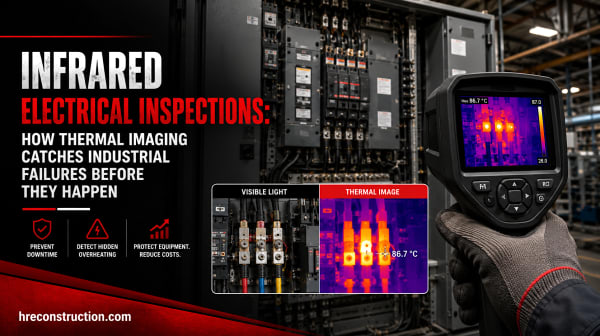 Infrared Electrical Inspections: How Thermal Imaging Catches Industrial Failures Before They Happen
June 30, 2026
Most electrical failures give off heat long before they give out. An infrared inspection reads that heat, turning an invisible...
 Signs Your Electrical System is Failing in a Manufacturing Plant
March 23, 2026
Electrical systems form the foundation of a manufacturing plant. From powering machinery to powering production lines, an...